Brownfield & revamping
Modifying an existing
industrial installation
Designing a modification without working from an assumed reality.
Adding a line, replacing an item of equipment, increasing capacity or reorganising a unit is a brownfield operation. The modification has to fit into an environment that is already built, in service, transformed over the years and sometimes imperfectly documented.
Moreau Engineering takes on that whole chain, from surveying the existing plant through to fabrication documents and site assistance. The 3D scan provides the geometry. Inspection and documents provide the technical context. Engineering turns the two into buildable decisions.
Since 2005 we have carried out process and piping design for existing industrial installations, working to our clients' own codes and documentation standards.
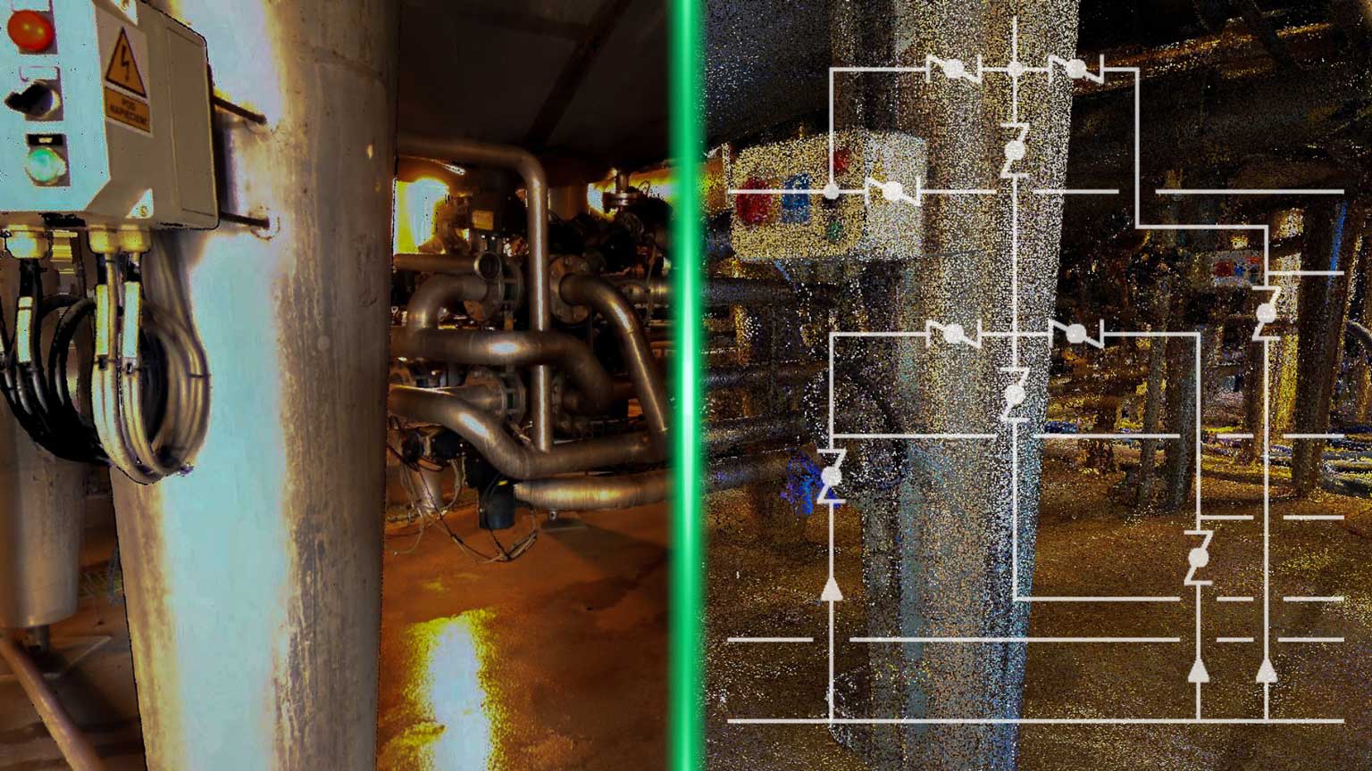
On an existing site, the first risk does not lie in the new routing. It lies in the gap between the installation as it stands and the representation used to design.
The drawings available usually describe an earlier state: original construction, the last documented extension, or an incomplete as-built dossier. Operation has continued since. Branch connections have been added, components replaced, supports moved and lines removed. Each of those changes may have been necessary and properly executed without ever reaching every affected document.
Our internal measurements confirm that this gap is structural. They cover eleven installations examined through repeated audit campaigns. Diameter is the only discrepancy we have met on every one of them; piping class and pressure rating follow, present on nine installations out of eleven. Among those three attributes, diameter and class account for close to nine discrepancies out of ten. This is not the trace of a few isolated errors: it is a regular pattern, and it rules out treating existing documentation as field truth without first qualifying it.
The consequence never stays confined to the document. A wrong DN can change the hydraulic calculation, steer selection towards the wrong component, corrupt the bill of materials and reach prefabrication. The discrepancy then surfaces during erection, once the shutdown window, the crews and the lifting equipment are already committed.
A wrong piping class affects material, wall thickness, joints, gaskets and admissible fittings. It can make the mechanical calculation, the material order and the documentary check mutually inconsistent. An inaccurate pressure rating can lead to selecting valves or flanges incompatible with the conditions retained. In each of these cases the initial error is documentary, but its consequence becomes technical, contractual and operational.
The recurring discrepancies of an existing installation
Removed lines that still exist in the documents
A line taken out of service is rarely erased from the P&ID or the layout drawing. It then occupies a notional place on a rack, keeps a number in the register, or sustains an ambiguity about the process. The opposite also occurs: a line present in the field can be missing from the dossier.
The consistency of the register has to be checked, not merely its graphical appearance. A line number assigned twice is among the discrepancies our audits meet on the great majority of installations. An ambiguous identification then propagates into the isometrics, the line lists, the purchase requisitions, the test dossiers and the isolation procedures.
Branch connections added over years of operation
A sampling point, a drain or a utility connection can be added during a shutdown without every document being revised. Geometry alone establishes that the branch is there; it does not establish its function, its status or its service conditions. The observation has to be brought together with the P&ID, the line register and what the operations team knows.
Valves that no longer match the diagram
Valve discrepancies between the diagram and the model are among the most frequently recorded. A replaced valve does not necessarily have the same envelope, the same face-to-face dimension, the same actuation or the same access requirement. For a revamping study, these differences bear on the connection, on removability, on maintenance access and sometimes on the supports.
Incompatible attributes on a single line
Diameter and piping class are by far the two attributes that diverge most: among the diameter, class and pressure-rating discrepancies we record, they account for close to nine out of ten. Inconsistent diameter within a single line, mixed classes along one route, and a wrong class at component level recur from one installation to the next.
These findings must be investigated. Some correspond to a genuine reduction, or to a class transition correctly designed but poorly documented. Others reveal a mis-assignment. The method is not to correct a value automatically: it is to make the discrepancy visible, to look for its justification, and to have the data that will feed the study formally validated.
Instrumentation different from the one used to prepare the work
Instrumentation is likewise among the recurring discrepancies between diagram and model. A relocated transmitter, a modified loop or an added function can affect the risk assessment, the operating sequences and the isolation procedure. Reconciling field, P&ID and asset data therefore has to happen before the revamping is defined in detail.
Modified supports and clearances
A support moved to free an access potentially changes the spans, the loads transmitted and the behaviour of the line under thermal expansion. The scan records its visible position, but it replaces neither the identification of the support type nor the mechanical check.
Insulation creates a further ambiguity. The scanner measures its outer surface; it does not reliably deduce the DN, the insulation thickness or the condition of the pipe underneath. On a dense rack, a few centimetres nevertheless decide whether a new line can pass, whether the weld is accessible, and whether a component can be removed.
Across all the surveys analysed, the median share of findings classified as critical stands at one third. The subject is therefore not merely tidying up the drawings. A critical finding is a point that has to be resolved before designing or intervening safely.
That share varies considerably from one installation to another, and the distance between a well-kept site and a documentary record left aside is substantial. That is useful information in itself: the real state of a dossier is not guessed, it is measured.
This qualification changes the way a project is prepared. Not every discrepancy calls for the same response. Some can be corrected in the documentation. Others require a further check, a process decision, a contact measurement, an insulation opening or validation by operations. The discrepancy register thus becomes an arbitration tool: it separates what is known, what is inconsistent, and what remains to be confirmed.
In a brownfield project, the tie-in point is not chosen on the shortest route alone. It governs the preparation of the shutdown, the possibility of isolating the section, the draining, flushing or inerting operations, access for welding and inspection, and the co-activity with neighbouring units.
The choice depends among other things on the nature of the fluid, on pressures and temperatures, on the actual position of the isolation devices, on the tightness expected of them, on the volume to be made safe and on the shutdown duration that can be accepted. A connection on a line that can be isolated during a planned shutdown, an intervention on a section to be drained and inerted, and a hot tap are not equivalent geometric variants. They belong to different intervention scenarios.
The decisive information is usually distributed among several parties. Process knows the service conditions. Operations know which parts can be isolated and under what conditions. Maintenance knows the real accessibility and the precedents. HSE sets the conditions for making the section safe. Engineering brings these constraints together and checks that they remain compatible with the routing, the supports, the prefabrication and the phasing.
That is why we investigate tie-ins from the survey onwards. The model does not merely serve to check that a line fits. It has to make it possible to check that the line can be built, inspected, operated and maintained under the scenario retained.
From field reality to a buildable design
Reality Baseline
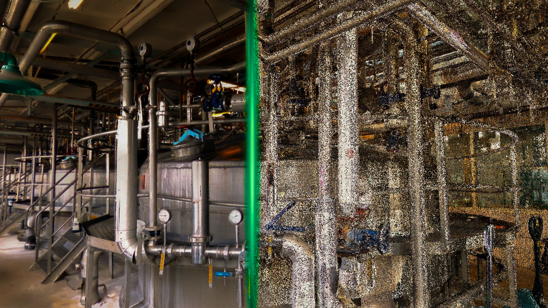
We begin by defining the useful scope: the area to be modified, the interfaces, the connections, the racks crossed, the accesses and the neighbouring equipment. The laser survey is carried out on site with a Trimble X7. The stations are registered into a coherent point cloud, deliverable in E57 format.
The point cloud is only one component of the reference. We complete it with visual inspection, spot measurements, reading of accessible nameplates and markings, and analysis of the available P&IDs, line lists, drawings and dossiers. Discrepancies are not silently corrected: they are recorded and qualified.
This reality baseline can be made available in SAMP.AI as a Shared Reality: a navigable 3D environment, associated P&IDs, searchable equipment, measurements and links to the available information. SAMP replaces neither Plant 3D nor the client's master systems. It provides a common context for understanding the existing plant and sharing decisions.
Brownfield Engineering
Design is carried out in AutoCAD Plant 3D and checked in Navisworks as required. We develop the layouts, the routing, the tie-in points, the calculation and flexibility notes, the supports, the fabrication isometrics and the bills of materials included in the scope.
The new model is checked against the Reality Baseline. Visible clashes are resolved before site work. Constraints that cannot be deduced from geometry are carried as assumptions or open points until they are validated.
Work preparation and site assistance
Deliverables are organised for tendering, prefabrication and erection. Depending on the scope, we support constructability reviews, the handling of technical queries, and the updating of documents after the work.
The aim is not to claim that every uncertainty can be eliminated. It is to move as much uncertainty as possible into the design phase, where it can still be arbitrated without consuming the shutdown window.
Digital Handover and Asset Continuity
After the work, the validated documents and the as-built state have to join the site's records. The point cloud, the model, the P&IDs, the isometrics, the bills of materials and the line register are handed over in the agreed formats. The Shared Reality can retain the useful links between geometry, diagrams and assets, while the CMMS, EDMS, ERP or SCADA remain the master systems.
This continuity prevents the next project from starting again from an obsolete snapshot. It rests first on clear governance: identified master systems, agreed formats, validation responsibilities and rules for updating after the work.
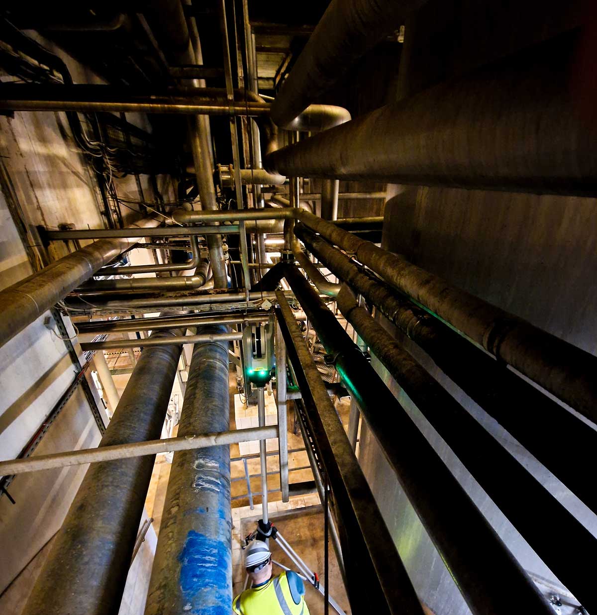
A scanner measures the surfaces visible from each station. It does not measure remaining wall thickness, does not on its own detect corrosion under insulation, and sees neither the inside of equipment nor occluded areas. It does not reliably deduce a material, a class or a service condition from a shape.
Shadow zones must therefore be identified in the survey. They can be reduced by additional stations, dealt with during a shutdown, or retained as explicit limits of coverage. Data that has not been observed must never be turned into graphical certainty.
Tags, flow directions, classes, materials and instrument functions come from several sources: visible markings, nameplates, documents, discussions with site teams and contact measurements. Where those sources diverge, we keep the divergence until it is arbitrated. A smooth model built on assumed attributes is more dangerous than one that shows its limits plainly.
A study is conducted within the client's own reference framework. Depending on the project this may include EN 13480 or ASME B31.3, the Pressure Equipment Directive 2014/68/EU, ATEX requirements, the piping classes, the line numbering convention and the site's support standards.
The delivery scope may comprise the E57 point cloud, the Plant 3D model, the revalidated P&IDs, the layout drawings, the calculation and flexibility notes, the support installation plans, the fabrication isometrics, the bills of materials and the discrepancy register. Each deliverable, its format, its input revision and its level of validation are defined at the scoping stage.
Send us the scope of the modification, the existing documents even if out of date, the applicable standards, the known service conditions and the milestones that govern the project: shutdown, tendering, material order or start-up. We return a structured first reading: usable data, visible inconsistencies, missing information, the survey scope we recommend, and the deliverables needed to move from an assumed existing state to a buildable brownfield design.
Frequently asked technical questions
Can the survey be carried out while the plant is running?
Most geometric acquisition is possible under normal operation, from authorised and accessible areas. That does not mean the whole scope will be visible. The inside of vessels, permanently isolated zones, occluded parts or areas under particular restriction may require a complement during a shutdown. Scoping therefore separates what can be surveyed while running, what can be surveyed under conditions, and what will remain unobserved.
Is the scan enough to choose the tie-ins?
No. It establishes the position and the visible environment of the possible connections. The final choice also depends on the process, on the possibility of isolation, on draining, flushing or inerting, on HSE conditions, on the window available and on construction access. These are worked through with the site disciplines.
Does a local modification require surveying the whole plant?
No. The relevant scope covers the area to be modified and the interfaces liable to decide the project. That may be a neighbouring rack, a load-bearing structure, a lifting access, equipment to be maintained, or a section needed for isolation. The right scope is neither the whole site nor the volume of the new equipment alone: it is the scope of the decisions to be taken.
What happens when the sources contradict one another?
We do not silently pick the most convenient figure. We record the discrepancy, its source and its potential impact. The data is then verified by further observation, by a reference document, or by validation from the competent discipline. Until that arbitration is obtained, it remains identified in the study as an assumption or an open point.
Does the data remain usable after the project?
Yes, provided the handover was defined at the scoping stage. The E57 cloud, the model, the line register, the P&IDs and the other deliverables must keep consistent identifiers and revisions. The value lies not only in each file, but in being able to trace the link between the asset in the field, the diagram and the document that describes it.
Method and sources
The proportions quoted on this page come from the internal analysis Moreau Engineering carries out on its own projects. They cover eleven industrial installations examined through repeated audit campaigns, and all surveys analysed for the severity of findings. Extracted on 19 August 2026: since the measurement is ongoing, these values are dated. We publish only aggregates covering five surveys or more, and never a figure traceable to an identifiable installation.
Written by Moreau Engineering, a piping and process design office based in Timișoara since 2005. Last reviewed: 19 August 2026. Our confidentiality commitments are set out on the Security and confidentiality page.
Read more
Our analyses
Every article starts from a pattern we have seen recur across several projects, never from an intuition. The scope of the finding and the date of extraction are given on each page.
19 August 2026
The Invisible Technical Debt of Brownfield Projects
A level of complexity that is often underestimated. Over the years a gap develops between the installation as it is documented and its physical reality — and it only becomes apparent the day someone sets out to modify something.


