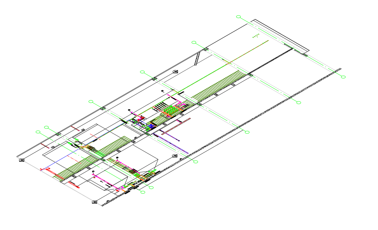
Plan of the
industrial installation
(piping)
Security &
Confidentiality
We place a high value on confidentiality and security. As a result, we provide each of our clients with their own private upload and download URLs and passwords on our local server. If you want to learn more about how we exchange documents, follow the link below:
Do you want to
Request an offer?
Thank you in advance for the interest you show in our company. The easiest way to request an offer is to contact us and discuss the details via e-mails or on the phone. You can contact us by clicking here:
EXAMPLES FROM PREVIOUS projects:
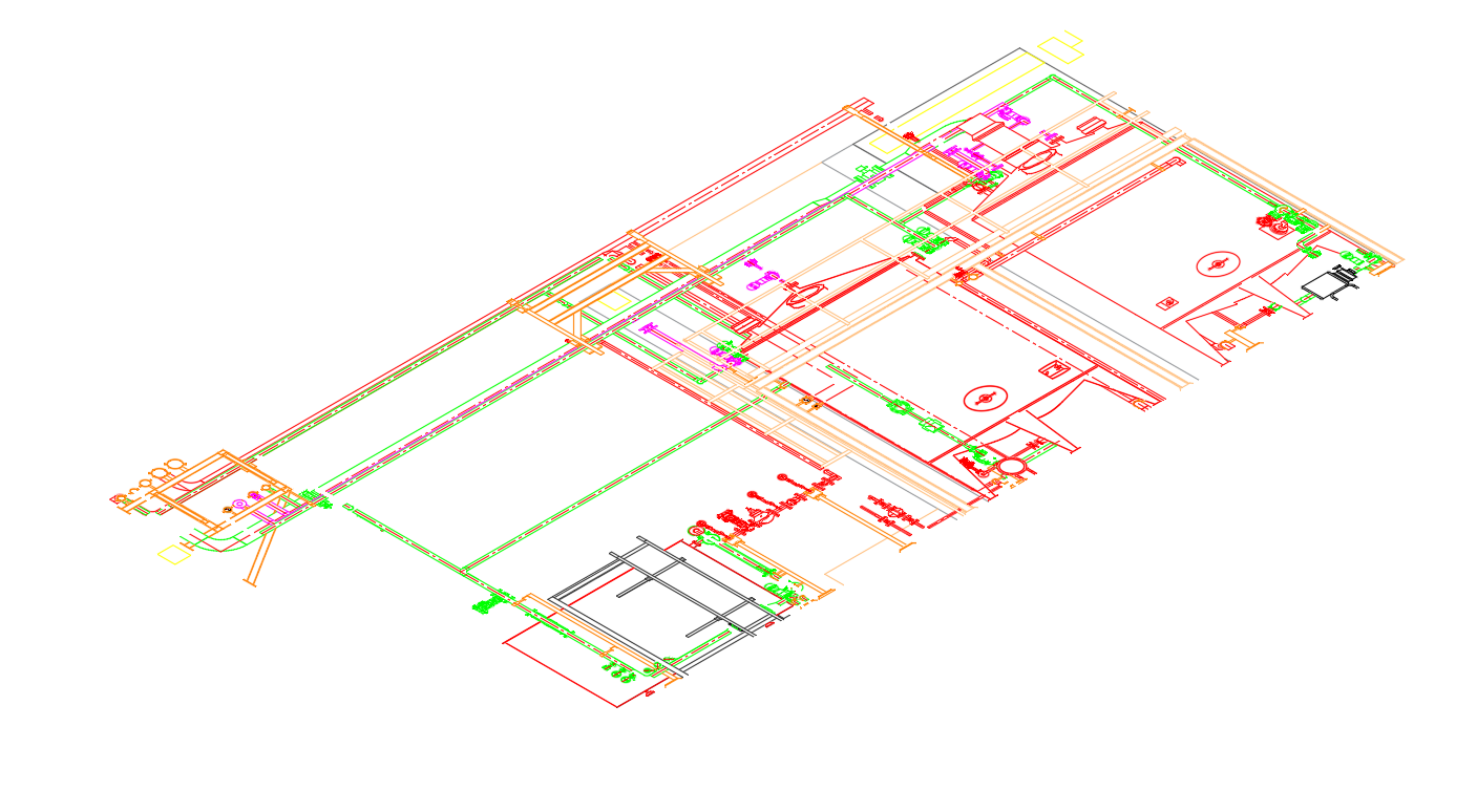


What the piping design we hand over contains
The model is the controlled technical baseline from which the drawings, the isometrics and the quantities are produced.
The 3D model
Modelling in AutoCAD Plant 3D. Every element carries its class, its material and its tag — these are not mere volumes.
The routing drawings
Layout of the networks by area and by level, extracted from the model.
The sections through dense areas
Everywhere a plan view is no longer enough to prove that it fits.
The interfaces with the other trades
Civil, structures, electrical, instrumentation: openings, shared supports, cable tray routes.
The clash detection
The model run through Navisworks, against the surveyed existing plant and against the other packages. Clash report handed over with the drawings.
The formats
DWG, PDF, native Plant 3D, or IFC exchange as agreed at the scoping stage.
The model is delivered by level of maturity
A 3D model is not either finished or unfinished. Our nomenclature follows it at 30, 60, 90 and 100 per cent, and each level serves a different decision.
Preliminary routing
Before the model: a preliminary route used to price the work and to check that the project fits into the volume available.
30 per cent
The main routes are set. This is the level where arbitrations are still free, and where the first bill of quantities becomes possible.
60 per cent
The secondary networks and the interfaces with the other trades. The bill of quantities tightens.
90 per cent
The details, the valves, the high and low points. The last level before the routing is frozen.
100 per cent
The model from which the isometrics and the final take-off are extracted.
The as-built
After the works, the model is revised from a field survey or from a 3D scan. That is what stops the next project from starting again from an obsolete picture.
The main pipe rack
Handled separately: preliminary routing, load calculation, then modelling from the 2D drawings, from a scan, or by integrating the vendor's model.
A model can be geometrically right and unusable for what follows. If the elements do not carry their piping class and their tag, the bill of materials will have to be re-entered by hand, and it will diverge from the drawing.
We therefore model with the specifications from the outset, which makes it possible to extract isometrics and bills of materials directly from the model. Re-entry disappears, and with it the main cause of divergence. Consistency between the model, the P&ID and the documents issued remains checked at every revision.