Detailed drawings
for installing
the supports
Security &
Confidentiality
We place a high value on confidentiality and security. As a result, we provide each of our clients with their own private upload and download URLs and passwords on our local server. If you want to learn more about how we exchange documents, follow the link below:
Do you want to
Request an offer?
Thank you in advance for the interest you show in our company. The easiest way to request an offer is to contact us and discuss the details via e-mails or on the phone. You can contact us by clicking here:
EXAMPLES FROM PREVIOUS projects:
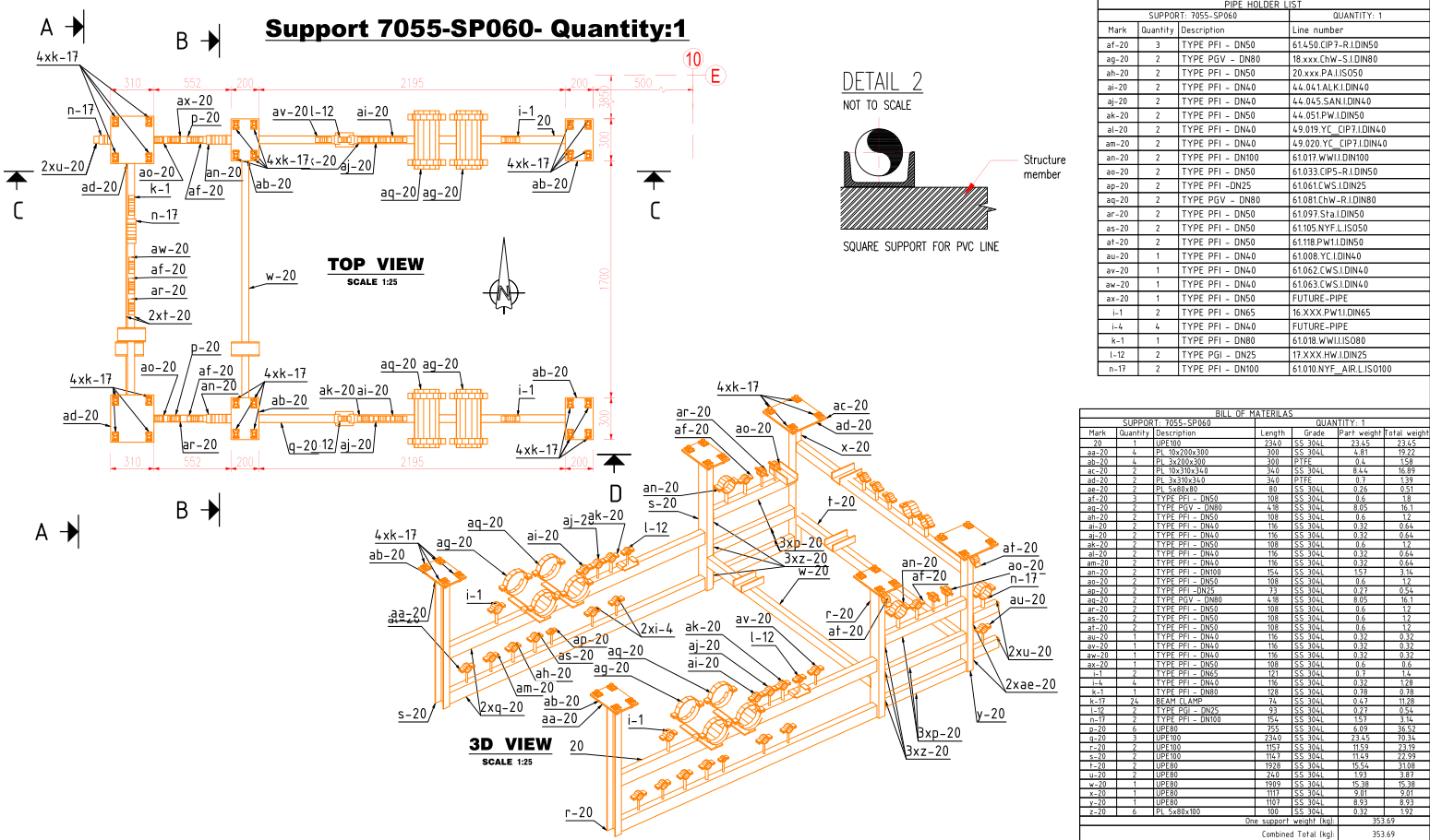
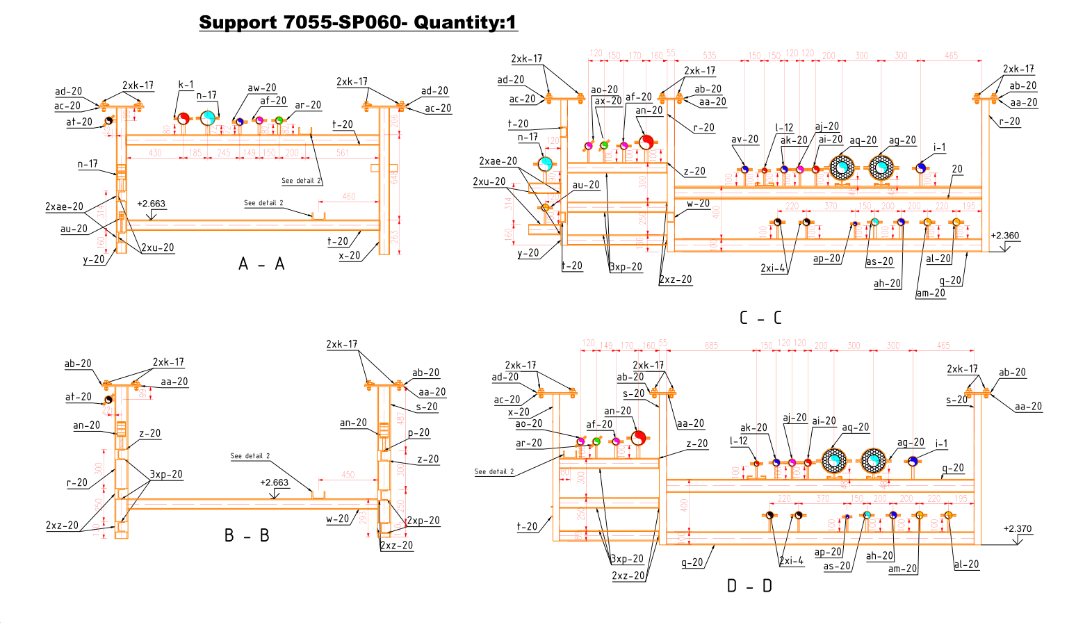


What the support dossier we hand over contains
It is designed together with the routing: it controls the movement of the line, transmits the loads to the structures and governs how the installation behaves in service.
The tagging of the supports
Every support identified, located on the drawings and attached to its line.
The type of each support
Anchor, guide, stop, sliding, spring. The choice follows from the behaviour of the line under thermal expansion, never from convenience of fixing.
The calculation notes
Flexibility and loads, to EN 13480 or ASME B31.3 depending on the framework applicable at your site.
The transmitted loads
Loads carried over to the structures and to civil engineering, in a form directly usable by the structural design office.
The detail drawings
Drawings of the non-standard supports, with their components.
The formats
DWG, PDF and a summary table usable for tendering.
Support work breaks down into five services
What is called a support dossier covers a calculation, a 3D model, a drawing, a bill of materials and a load note. The five are not delivered at the same moment.
The piping load note
The preliminary routing makes it possible to build the calculation model; the flexibility analysis then determines the movements, the loads and the stresses. Its results may lead to changing the routing, the position of a support or its function before the model is frozen.
The main pipe rack load note
Handled separately: a rack takes the loads of dozens of lines, and it is civil engineering that is waiting for it.
The supports in 3D
Modelled within the model, with their type. That is what makes it possible to check they clash neither with the other networks nor with the accesses.
The 2D support drawings
The shop and site document, with dimensions and components.
The bill of materials for the supports
Extracted from the model, for procurement.
A badly guided hot line does not break during erection. It fatigues, it eventually leaks at a flange, or it transmits its loads to an equipment nozzle that was not made to take them. The failure appears months after start-up, and its cause is then hard to establish.
We therefore carry out the flexibility calculation before freezing the routing, and not to justify after the event a route already drawn. When the calculation forces a change of routing, it is better to discover it on the model.