Engineering:
Process & PIPING
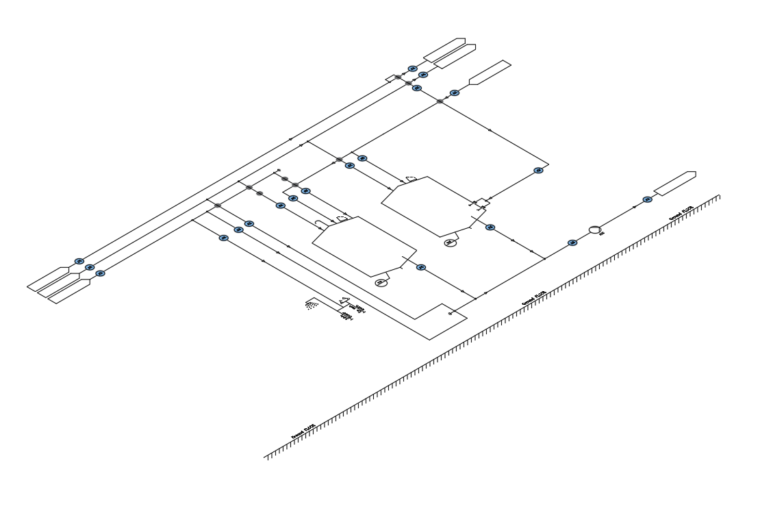
ㅤㅤㅤ"Based on the specifications, we create process flow diagrams PFD in accordance with your codification and symbolizing standards.
ㅤㅤㅤOn the process flow diagrams (PFD), the main equipment is presented (tanks, pumps, heat exchangers, etc.) with specific benchmarks, process lines, control valves
and main valves, which interfere in the process.
ㅤㅤㅤWe also represent the control loops (automation), various information related to the process (flow, pressure, temperature, etc.)
for the minimal and maximal conditions, respectively and the type of fluid conveyed."
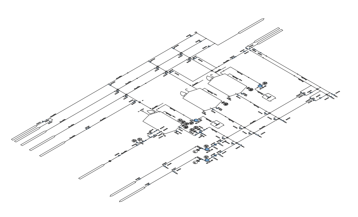
ㅤㅤㅤ"Based on the specifications and/or by analogy, we set up P&ID (Piping & Instrumentations Diagram).
ㅤㅤㅤP&ID represents all the equipment, all the process lines, utilities lines connected to the process ones and/or to the equipment, process and utilities valves,
adjustment loops (automation), measurement instruments, process information (volume, flow, temperature, pressure).
ㅤㅤㅤWe also represent all the types of accessories, purges, special connections, sampling valves, reductions, flanges, fluid direction and material class changes.
ㅤㅤㅤWe indicate line, accessories and equipment benchmarks. We draw up the bill of materials based on the P&ID."
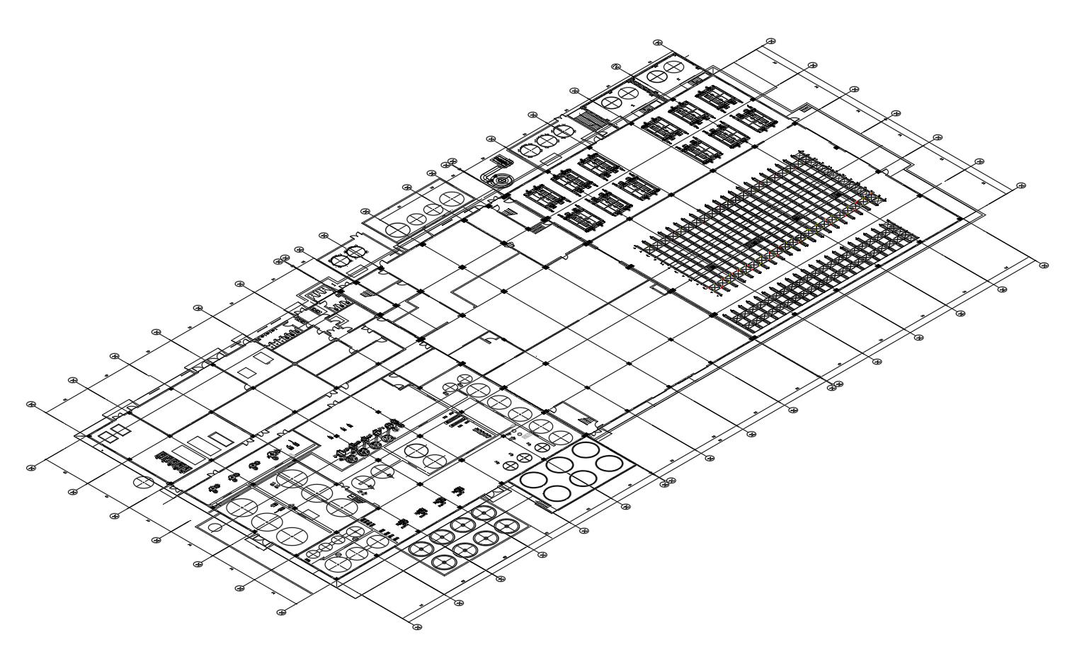
ㅤㅤㅤ"We draw up the general plan of a plant depending on the process areas and/or depending on the specifications mentioning all the equipment of a site and/or PID.
ㅤㅤㅤThese plans may be used by the customer when obtaining various permits (environment, construction, etc.).
ㅤㅤㅤIn a new installation or the upgrade of an existing installation, we draw up location plans on which we place the equipment, considering the volume occupied by them, space ergonomics, the areas needed for logistic, the access areas needed for maintenance and future expansions.
ㅤㅤㅤAt the same time, we take into account the internal segments for the process and utilities lines and cable trays (power cables and controls)."
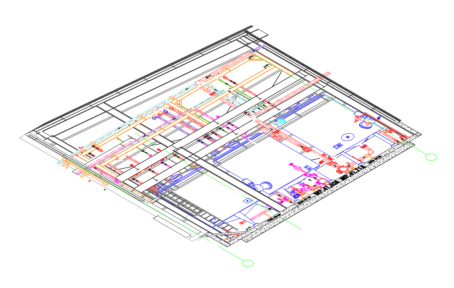
ㅤㅤㅤ"We draw up plans of the industrial installation (piping) starting from the process flow diagrams, equipment location plans, building construction plans and equipment plans.
ㅤㅤㅤIn order to draw the plans, we work both in 3D and 2D. On these plans, we represent the environmental elements (building structure), relevant equipment, pipes, fittings, accessories, etc.
ㅤㅤㅤWe also draw up all the details and sections needed to facilitate the understanding of the installation. We indicate on these plans the equipment benchmarks, line, valves and accessories benchmarks and the sizes of the main equipment."
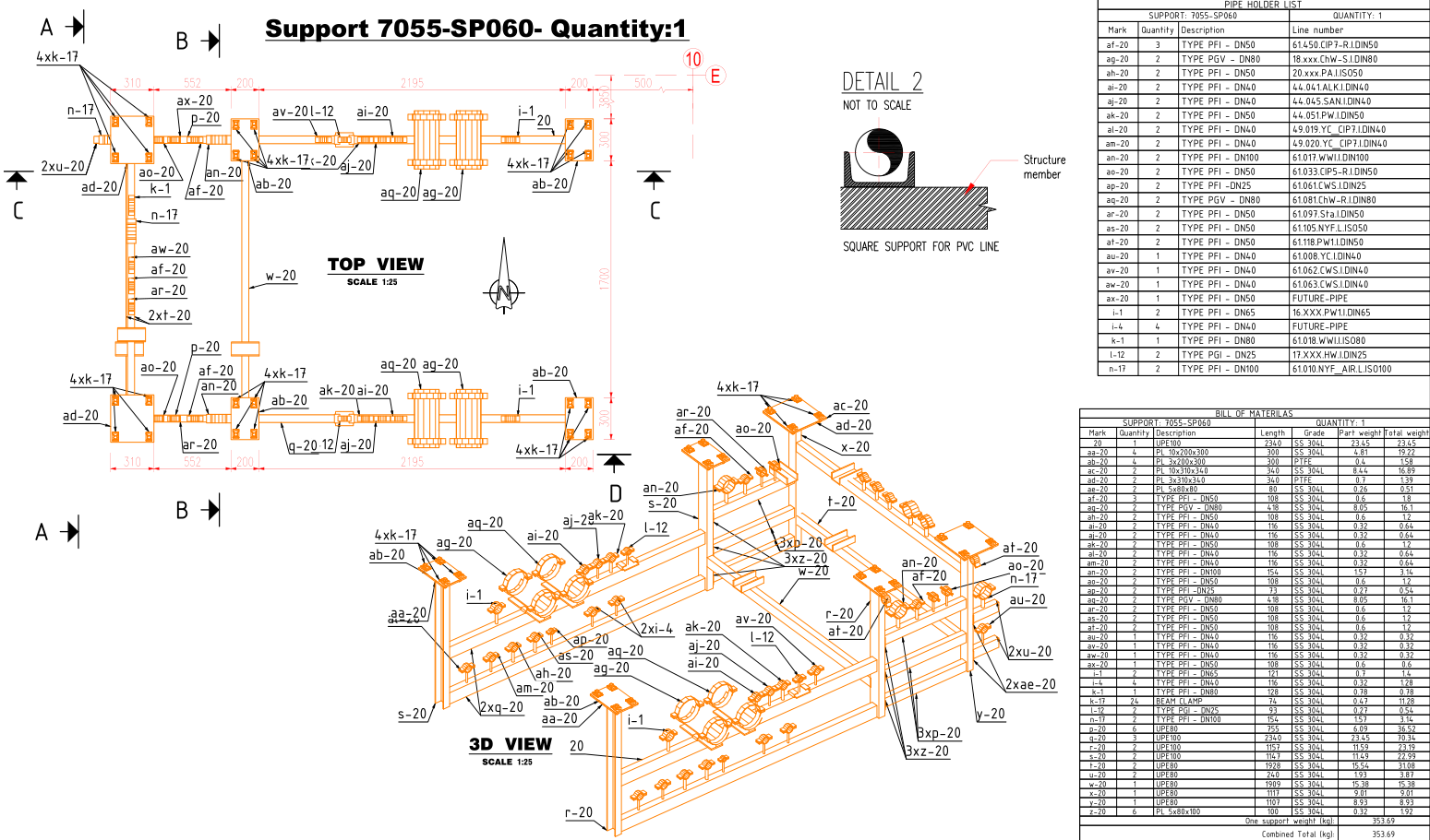
ㅤㅤㅤ"According to the specification and pipe standards, we draw up detailed plans for the installation of supports.
ㅤㅤㅤIn order to facilitate their installation on the site, the supports are marked and identified on the plans of the installation and/or on the isometric plans."
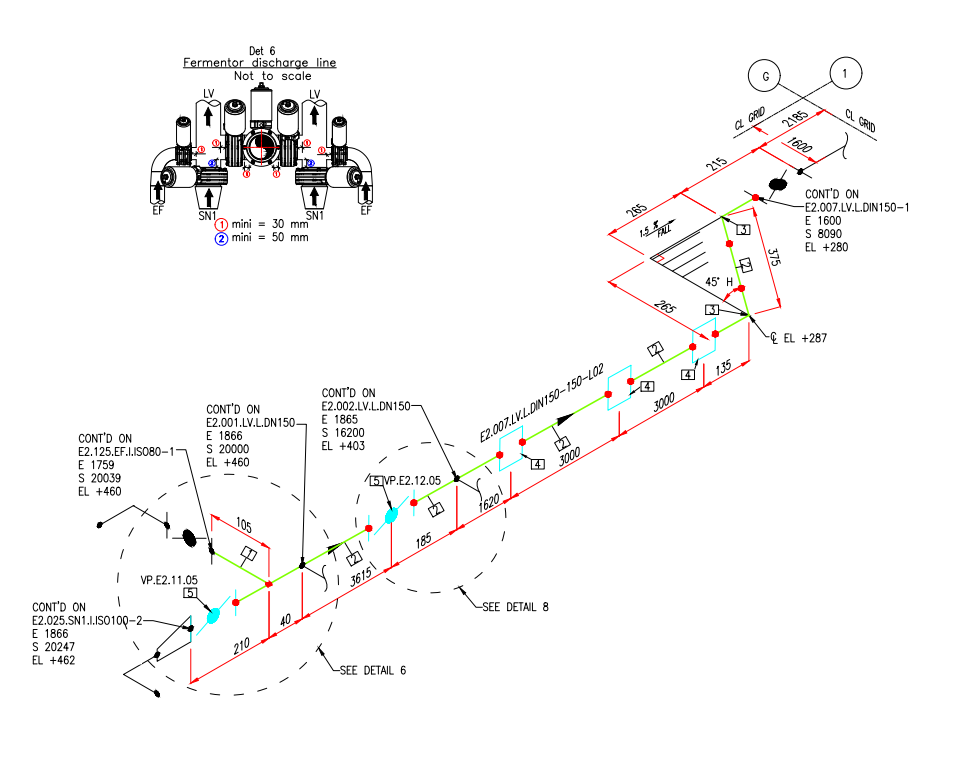
ㅤㅤㅤ"These are indispensable documents for the plumber.
ㅤㅤㅤThe isometry (axonometry - is the representation of a line in isometric view) comprises all the elements needed to set up the line:
ㅤㅤㅤThe centralizer incorporates all the accessories of the installation (angle pipes, branch pipes, etc.),
the materials needed (valves, filters, check valve, etc.) and references to the general plan of the installation and/or
the process flow diagram.
ㅤㅤㅤFor consultations and purchases, we make lists of equipment (valves, dampers, filters, valves, etc.)
according to process diagrams, bill of materials derived from isometric measurements (axonometry)."